


QBT Low-voltage switchboards
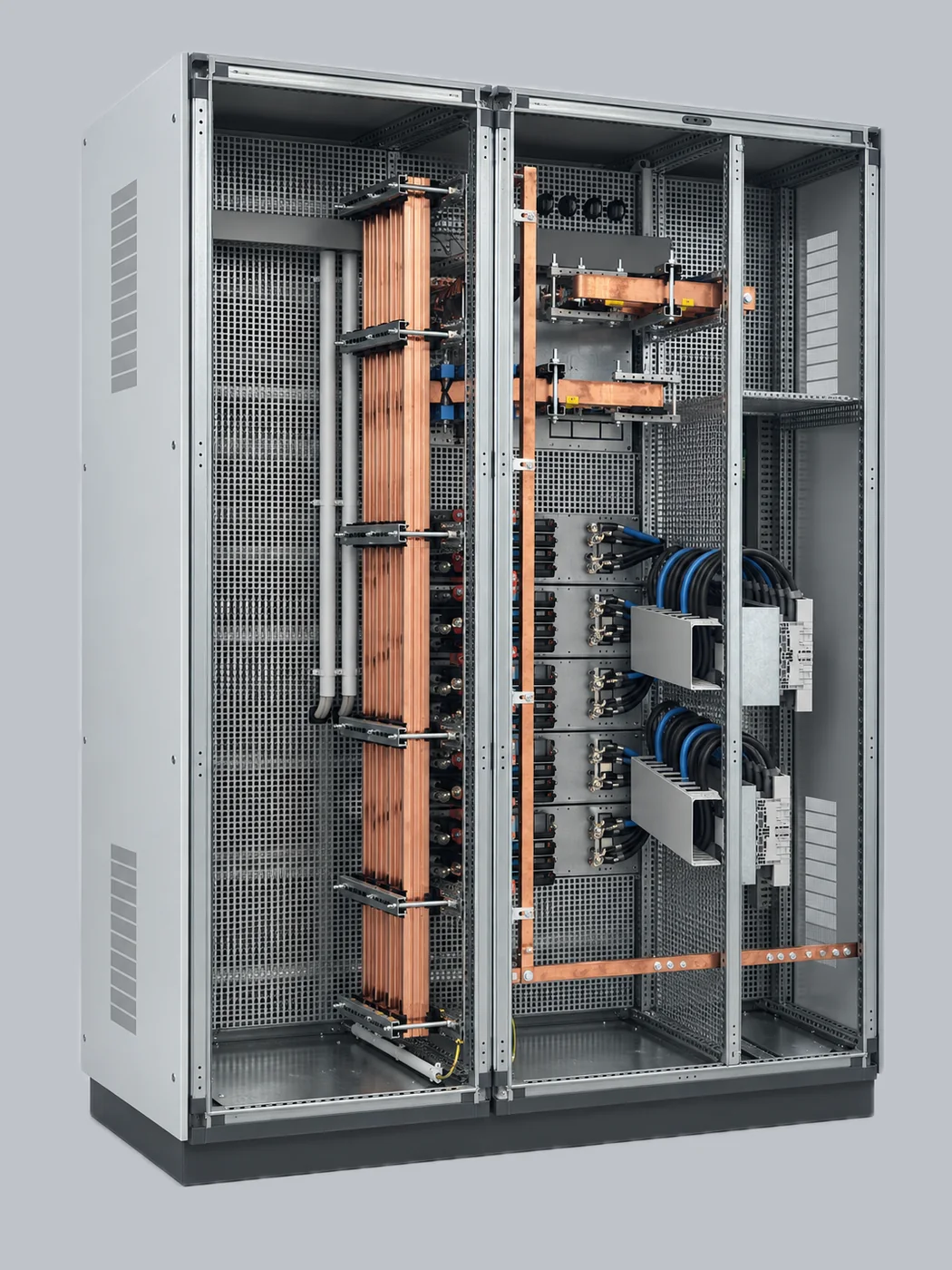 Copper busbars, flat or shaped
Front, rear or side access
Galvanised and painted sheet steel
Modules from 600 to 2000 mm high
LV switchboards designed, manufactured and tested by CEP. Up to 6300 A and 120 kA for 1 s, compliant with CEI EN 61439-1, -2 and -3, for MV/LV substations, residential and industrial installations, photovoltaic, wind and energy storage systems.

CEP LV switchboards
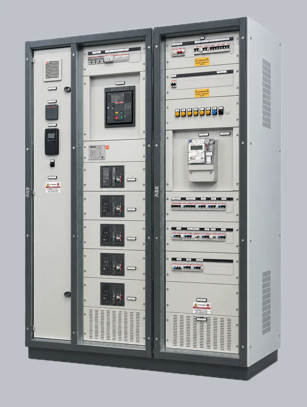
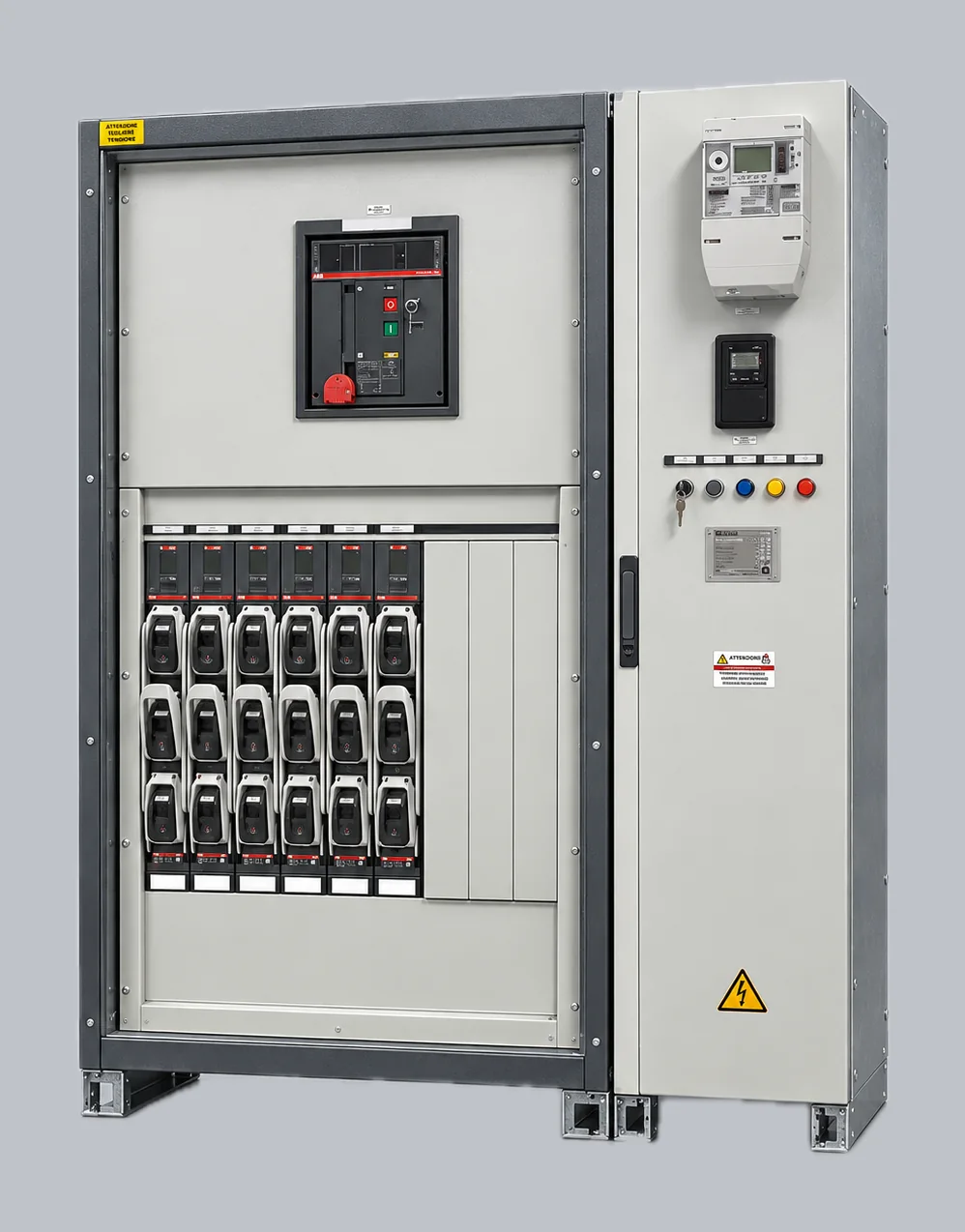
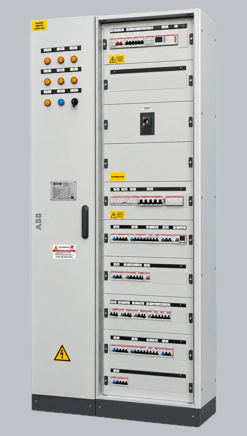
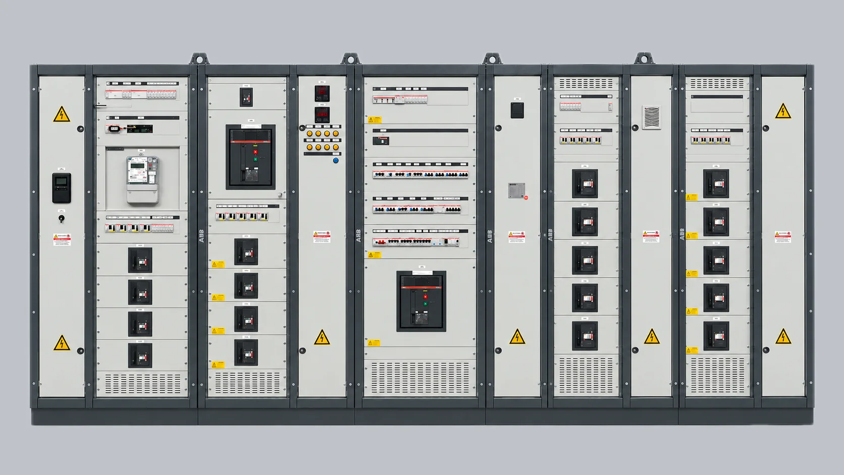
It starts from the plant diagram. Copper busbars, flat or shaped, seven forms of internal separation, front, rear or side access: every switchboard is configured on the project, even outside the standard range.
The switchboard in numbers
- Rated operational current
- 6300A
- Short-time withstand current Icw · 1 s
- 120kA
- Peak withstand current Ipk
- 330kA
- Maximum DC voltage
- 1500Vdc
- Forms of internal separation, from 1 to 4b
- 7forms
How they are built
For MV/LV transformer substations, residential and industrial installations and renewable energy plants: photovoltaic, wind, energy storage systems.
-
Designed and built in our own plant
The switchboard is designed by CEP on the plant diagram and built in Calatafimi Segesta, in the same plant as the substations.
-
Up to 6300 A
Rated operational current up to 6300 A, short-time withstand current 120 kA for 1 s and peak current 330 kA.
-
CEI EN 61439 compliance
Design verification and routine verification according to CEI EN 61439-1, -2 and -3.
-
Seven forms of internal separation
From form 1 to 4b, chosen according to the level of separation required by the plant and by maintenance procedures.
-
Indoor or outdoor
Degree of protection from IP30 to IP65 for outdoor installation, IP20 indoors. Mechanical impact resistance IK08, IK09 or IK10.
-
Modular dimensions, custom sizes on request
Heights from 600 to 2000 mm, widths from 300 to 1250 mm, depths from 200 to 1250 mm. Non-standard sizes to specification.
-
Access and maintenance
Front, rear or side access depending on the configuration. Architectures that allow work on a single outgoing feeder without disconnecting power from the rest of the switchboard.
-
Documentation ships with the switchboard
Design is carried out in house and extends to the documentation that accompanies the switchboard on site: single-line, multi-line and detailed electrical diagrams, bills of materials, vendor list, maintenance manual, declaration of conformity.
Eight modular heights, from 600 to 2000 mm
Widths from 300 to 1250 mm, depths from 200 to 1250 mm. Non-standard sizes to specification.
- 600 mm
- 800 mm
- 1000 mm
- 1200 mm
- 1400 mm
- 1600 mm
- 1800 mm
- 2000 mm
Rating plate data of the range
Mechanical characteristics
- Enclosures
- metal, in galvanised and painted sheet steel · thermoplastic
- Configurations
- wall-mounted or floor-standing monobloc enclosures · floor-standing modular cabinets
- Non-standard dimensions
- on request
- Accessibility
- front · rear · side
Electrical characteristics
- Rated operational voltage
- 400 · 600 · 690 · 800 · 1000 Vac · up to 1500 Vdc
- Rated insulation voltage
- up to 1000 V, depending on the configuration
- Rated impulse withstand voltage
- 2,5 · 4 · 6 · 12 kV
- Rated frequency
- 50 · 60 Hz
- Rated operational current
- up to 6300 A
- Short-time withstand current Icw (1 s)
- 120 kA
- Peak withstand current Ipk
- 330 kA
- Reference standards
- CEI EN 61439-1 · CEI EN 61439-2 · CEI EN 61439-3
Distribution systems
- Main circuits, standard
- flat or shaped copper bars
- Main circuits, on request
- flat or shaped aluminium bars
- Auxiliary and control circuits
- distribution blocks · certified distribution kits
Module height · mm
- 600
- 800
- 1000
- 1200
- 1400
- 1600
- 1800
- 2000
Module width · mm
- 300
- 400
- 600
- 800
- 1000
- 1250
Module depth · mm
- 200
- 250
- 300
- 500
- 700
- 900
- 1250
Forms of internal separation
- 1
- 2a
- 2b
- 3a
- 3b
- 4a
- 4b
Degree of protection, outdoor
- IP30
- IP43
- IP55
- IP65
Degree of protection, indoor
- IP20
Mechanical impact resistance
- IK08
- IK09
- IK10
Standard modular sizes. Non-standard sizes on request.
Where they work
-
MV/LV substation
Substation QBT
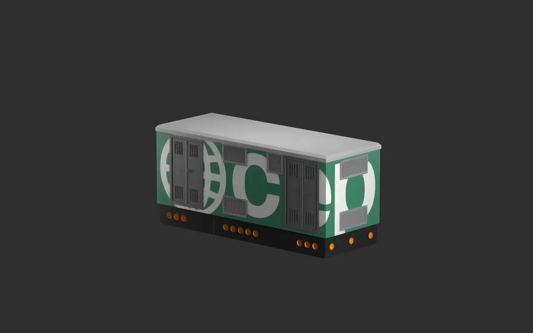
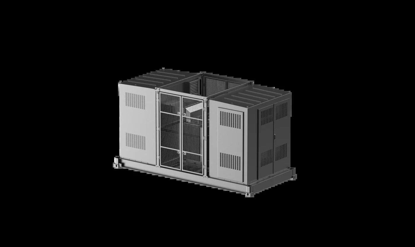
Main switchboard of the substation, sized on the transformer and the outgoing loads. Designed to sit inside a CEP substation, CAV or container, and supplied already wired and tested together with the rest of the substation.
-
Buildings and infrastructure
Distribution QBT
Secondary distribution for power plants, buildings, industrial plants and infrastructure. Number and size of the outgoing feeders follow the customer's single-line diagram.
-
Industry
Power center QBT
Primary low-voltage distribution for industrial plants, permanent or temporary. This is where the top sizes of the range are used: 6300 A rated current and 120 kA for 1 s short-circuit withstand.
-
Photovoltaic · Wind · Storage
QBT for renewable sources
Inverter line paralleling in photovoltaic plants, field and conversion switchboards in wind farms, AC-side switchboards in storage systems. Including the main and auxiliary switchboards serving the substation.
-
Electric mobility
QBT for charging infrastructure
From the delivery point to the charging stations: distribution, selective protection, metering for each charging point and remote supervision.
QBT E-Mobility
From the plant to the substation
-
Design
On the plant diagram, extending to the documentation that accompanies the switchboard on site.
-
Production
Five parallel production cells, with in-process controls and lean management methods.
-
Testing
Functional testing, then the warehouse: packing and shipping to the customer, or the CAV cells.
-
In the substation
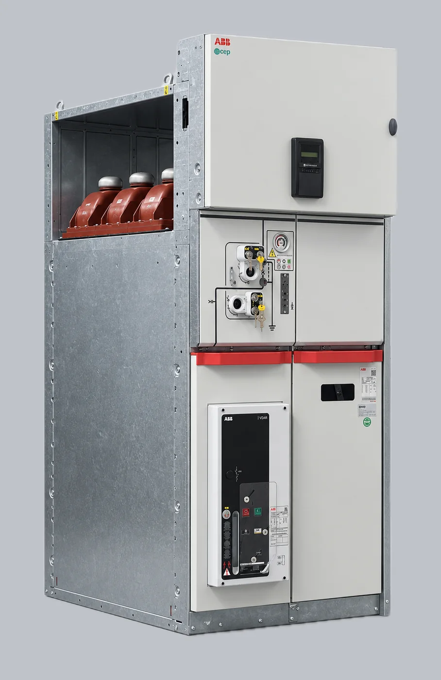
Installed, wired and tested together with the transformer and the MV switchgear. The substation leaves the plant ready for commissioning.
Contact us!
For information or a quote on an LV switchboard, please send us the plant diagram if you have it, the currents involved and the type of installation.